NAVSEA JOURNAL
May, 1975
SUSPENDED SUBMARINE SYSTEM
by
G. D. Campbell, SM4
Naval Underwater Systems Center
Newport, Rhode Island
The Naval Underwater Systems Center has been tasked by the Naval
Sea Systems Command (PMS 402) to design, fabricate and operate a system
capable of repeatedly and reliably lowering and raising a modified decommissioned
submarine to a maximum depth of 300 feet for use as a target for exercise
and inert loaded Mk 48 Mod 1 Torpedo runs. The ex-Menhaden (SS-377) has
been designated for the program. Built by the Manitowoc Shipbuilding Company,
the SS-377 was deployed in July 1945. Conversion to a Guppy IIA took place
in 1953 and the submarine was deactivated in 1971. It is currently moored
at the Naval Inactive Ship Maintenance Facility, San Diego, California.
The suspension method being developed is a modification of the suspension
system developed by NUSC (New London Laboratory) and used successfully
to suspend the USS Trigger (SS-564) and other submarines in the mid-late
sixties for the target characteristics measurements project (reference
1).
MK 48 Weapon Application
The primary objective of this program is to provide a real submarine
target for the torpedo Mk 48 Mod 1 weapon system. Past evaluations have
produced large quantities of useful data against artificial electronic
targets, both moving and stationary such as the target Mk 17 and the mobile
target Mk 27. There now exists a need for torpedo performance data against
real targets, particularly against real submerged submarines. Safety considerations
have prevented the gathering of this type of data, particularly in the
areas of close-in dynamic and acoustic performance and warhead/exploder
performance of the type that can be gained from "near-miss" and "hit" shots.
An in-water run program will be generated to obtain these needed data.
A portion of these runs will impact the submarine; at least five runs will
be of this nature -- hardware considerations permitting. The torpedo runs
will be conducted at the Naval Torpedo Station, Keyport, Washington, 3-D
acoustic tracking ranges, Dabob Bay and Nanoose. Although past studies
have indicated hull penetration is unlikely, for the first two impact runs,
the submarine will be positioned in the shallowest portion of the Dabob
range where the shallow water will enhance any possible required submarine
salvage operations. After these initial tests for hull integrity, the remaining
runs will take place at Nanoose where better acoustic conditions prevail.
A live torpedo run (SINKEX) is being contemplated after completion of the
inert torpedo run program, but only after other potential users of the
submarine suspension system have had the opportunity to conduct any required
tests and programs.
Suspension System
Figure 1 (not shown), an artist's concept of the submarine suspension
system, shows the overall approach being used. Repeated use of this system
requires that it be reliable and safe. Other requirements initially imposed
on the system are simple and reliable operation and that it be recoverable
from casualties, transportable and operable in moderate sea states (3 -
5) and survivable in higher sea states. The submarine will be suspended
in a slightly negative buoyant (2k - 6k lb) condition from two long, thin
cylindrical buoys attached fore and aft by 10-ton swivels and dynagrips
fixing the cable ends to the submarine. The buoy shape is chosen to minimize
the effects of sea states. Initial trim suspensions will be conducted by
adjusting the amount of water in the fore and aft trim tanks and auxiliary
tanks, the submarine having been already modified to permit this operation.
Lowering and raising the submarine to a maximum depth of 300 feet will
be accomplished by means of hydraulic cable pullers and cable take-up winches
within each supporting buoy. These will be powered by a diesel powered
hydraulic power package on board a nearby service ship. Quick disconnect
hydraulic fittings are used to permit the service ship to depart during
torpedo runs.
Communications between the service ship and the submarine will
be via a radio link and it's own buoy housing a transceiver, power pack
and connected to the submarine with an umbilical cable. The function of
this subsystem is twofold. First and primarily it transmits submarine status
signals (depth, pitch, compartment flooding, HP air, etc.) to a display
console on the service ship. Second, the operator on the service ship can
send a command to blow MBT and FBT tanks in the event of an emergency (hull
rupture, etc.). An automatic blow is designed into the system in case of
radio link communications loss for any reason such as control room flooding
from a torpedo impact. This automatic blow feature can be inhibited by
the operator when personnel are working in the vicinity of the submarine.
The operator can also set in an adjustable delay to prevent blowing when
communication is temporarily lost due to high sea states. A compartment
flooding or detonation sensor will cause an automatic blow. An additional
source of data will be from the suspension buoys themselves which will
be calibrated in 1 ton stripes. The amount of submergence will indicate
the weight of the buoy.
To enhance diver and camera inspection after each impact, the
submarine will be painted a high visibility yellow. Each tank bulkhead
will be painted with a black stripe and each tank number painted on the
tank in large black letters to facilitate diver identification of the exact
location of damage.
Trim System Modifications
Modifications and refurbishments to the submarine itself are
covered in detail in reference 2. Rather than attempt to cover the details
of all submarine modifications in this article, one particular example,
that of adjusting the initial trim and buoyancy, will be discussed. The
trim and buoyancy are attained by adjusting the amount of water in the
auxiliary tanks and forward and after trim tanks until both suspension
buoys have settled to a predetermined depth. Modifications permit this
to be performed externally by divers with a nearby service ship equipped
with a water pump and air compressor. Figure 2 (not shown) shows these
modifications as a simplified schematic and the following two paragraphs
describe the submarine modifications required to fill and empty the auxiliary
and trim tanks.
The forward portion of the trim manifold will be removed, the
trim line to negative will be blanked, and the flanged connections for
the forward and after trim tanks will be reduced for the attachment of
two new filling lines running through the hull. All valves on the remaining
portion will be wired shut except auxiliary tanks, 1 and 2, effectively
combining these two tanks. A third line for filling the auxiliary tanks
will be attached and run along with the previous two new lines through
the hull. External to the hull these three lines will terminate with valves
and caps. The desired tank can be filled from the service ship by a diver
connecting a water hose, opening the valve to the air pipe described below.
To empty the tanks, all tanks will be commoned at the 225 lb
manifold and a single air line running through the hull alongside the three
filling lines and terminating with a valve and cap. To do this, all valves
on the 225 lb manifold will be locked shut except the four blow valves
to the forward and after trim tanks and two auxiliary tanks. The service
air hose connection valve will be removed and the previously mentioned
pipeline running through the hull will be attached. Emptying the tanks
is accomplished by a diver supplying 50 lb air to this line and opening
the fill valve and cap to the tank being emptied.
Submarine Modifications
Additional submarine modifications will be discussed briefly.
The high pressure air system and the 600 lb manifold will be modified to
permit dockside charging and emergency blowing command through the radio
link or by events such as flooding. The vent system modifications permit
opening and closing the vents by divers connecting hydraulic lines externally
while the submarine is on or near the surface. All normal fuel oil tanks
will be free flooding with diver access permitted. The bow buoyancy tank
will be free flooding. The forward and after torpedo rooms will have foam
blocks installed to reduce the floodable volume. Depth sensors and flooding
sensors will be installed and data transmitted to a submarine console (part
of the radio link system). All remaining masts will be removed and the
openings blanked. All unused hull penetrations will be blanked. Navigation
lights will be installed according to the Rules of the Road for vessels
under tow. The depth charge dogs will be attached and the strongbacks will
be in place. Fairing plates will be installed over the after torpedo exit
channels. All compartments will be checked for leakage. All batteries will
be filled with fresh water after testing for chlorides. These previous
items, while not all-inclusive nor given here in great detail, should be
sufficient to convey the nature and magnitude of the modifications required
for the ex-Menhaden.
Schedule
Current plans are to have the submarine suspension system operational
during the second quarter of FY 1976 with the torpedo Mk 48 operations
(except the SINKEX) complete in the third quarter of FY 1976. Since a suspended
submarine system could have potential use for other ASW programs, the submarine
could be made available to other programs prior to any consideration to
a SINKEX.
References
1. NAVAL UNDERWATER SOUND LAB (U) Technical Memorandum 221-277-69,
"Buoy Assisted Submarine Hovering System (U)," F.P Fessenden and F.J. Keltonic,
22 September 1969, UNCLASSIFIED.
2. SUPSHIPS 11th Naval District (U) Sketch No. 3081, "Shipboard
Investigation/Concept and Engineering Recommendations for the ex-USS Menhaden
(SS-377)" 27 September 1974, UNCLASSIFIED.
(The Above Information Courtesy of Ron Reeves, Retired HTC)
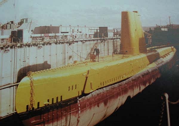 The USS Menhaden (SS-377) undergoing the "suspended submarine
system" modifications at the Naval Ocean Systems Center drydock in San
Diego, California.
(Image Courtesy of Don Morris, EN1(SS), Menhaden, 1966-69)
The USS Menhaden (SS-377) undergoing the "suspended submarine
system" modifications at the Naval Ocean Systems Center drydock in San
Diego, California.
(Image Courtesy of Don Morris, EN1(SS), Menhaden, 1966-69)
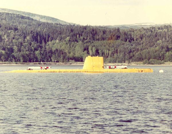 View of the USS Menhaden (SS-377) after all of the modifications
described above were completed and she was towed to Keyport, Washington.
(Image Courtesy of Steve Bell, RM2(SS), Menhaden, 1963-65)
View of the USS Menhaden (SS-377) after all of the modifications
described above were completed and she was towed to Keyport, Washington.
(Image Courtesy of Steve Bell, RM2(SS), Menhaden, 1963-65)